반사전력은 공정에 결합되지 않고 발생기로 다시 돌아오는 생성된 마이크로파 전원의 일부로 정의된다. 마이크로파 공정에서, 이 매개변수는 가열할 재료나 플라즈마로 들어가는 마이크로파 에너지 전달의 효율성을 평가하는 데 사용되는 중요한 매개변수이다. 이 논문에서는 반사전력 값의 의미, 마이크로파의 반사도에 영향을 주는 매개변수, 및 반사전력을 최소화하는 방법에 대해 설명한다.
마이크로파 플라즈마 시스템의 장점 중 하나는, RF(무선 주파수) 플라즈마 시스템과는 달리, 반사전력이 직접적인 손상을 유발하지 않으며, 공정 최적화에 사용할 수 있다는 것이다.
마이크로파 (-플라즈마) 시스템에 대한 설명
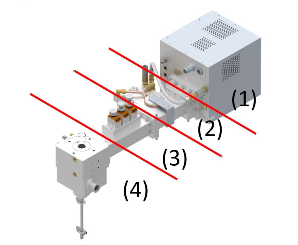
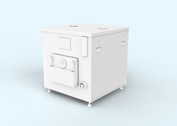
다음 예시 에서는, 전형적인 마이크로파 플라즈마 시스템이 대기 연소기 모델을 사용하여 설명된다.
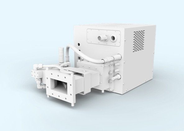
그림 1: 마이크로파 시스템의 기능적 모델: (1) 마이크로파 발생기, (2) 아이솔레이터, (3) 3-스터브 튜너, (4) 대기 연소기(모든 용도에 사용 가능)
고전압 전원공급장치(보통 스위칭 모드)에 의해 구동되는 마이크로파 발생기는 마그네트론을 통해 마이크로파 전원을 생산한다; 그림 1의 주파수는 2.45 GHz이다.
아이솔레이터는 2포트 장치인데, 이것은 마이크로파 전력이 마이크로파 발생기에서 부하로 전달되지만, 반사전력이 생성되는 경우에는, 마그네트론/발생기로 되돌아 가지 않는다. 이러한 장치의 가장 일반적인 용도는 반사전력이 불러 올 수 있는 손상 효과로부터 마그네트론을 보호하는 것이다. 아이솔레이터 입구에서, 반사전력(일반적으로 흡수력이 약한 부하에 의해 생성됨)은 완벽하게 물 (water load)로 전환되고 흡수되며, 순환수에서 열로 소멸된다.
3-스터브 튜너는 마그네트론의 임피던스를 부하의 임피던스(예: 플라즈마)와 매칭시켜 시스템의 넓은 공정창을 허용하는 선택적 구성요소이다. 매우 동적인 프로세스의 경우, 튜너를 자동으로 실행하는 것이 유용하다. 그러나 공정이 약간의 변화를 겪는다면, 즉 마이크로파 커플링에 안정적이라면, 임피던스는 공정 시작부터 영구적으로 매칭될 수 있다. 이 경우, 매칭은 개별적인 고정 튜닝 요소를 통해 수행할 수 있다.
대기 플라즈마 소스(APS) 대표 부하
임피던스 부정합(mismatch)을 유발하는 반사전력
근본 원인
플라즈마 시스템의 구성요소(예: 마이크로파 발생기 및 플라즈마 소스)가 제대로 매치하지 않으면, 항상 반사전력이 발생한다. 마이크로파 공정에서, 이는 도파관 형상, 선 형상(동축 도체, 스트립라인 등)의 변화로 인해 발생하지만, 또한, 공정 챔버의 유전체 부하 변화로 인해 발생한다. 따라서 마이크로파 커플링은 공정 물질의 변화, 증발하는 물, 플라즈마 점화, 온도, 압력 등으로 인해 달라질 수 있는데, 이로 인해 반사전력을 감소시키려면 임피던스 매칭을 조정해야 한다. 이러한 변경 사항이 시스템에서 갑자기 발생할수록, 매칭하는 단일 요소와의 부정합을 보상하기가 어려워진다.
이러한 모든 효과는 임피던스 매칭에 의해 설명될 수 있으며 Smith 도표를 통해 시각화할 수 있다. 생성기와 부하는 (주파수 의존성) 복합 임피던스에 할당될 수 있는데, 이들은 복잡한 매칭 네트워크에 의해 일치된다. 매칭 네트워크는 이상적으로 저항성이 없는 인덕터 및 커패시터에 의해 구축된다. 그림 1의 경우, 이는 튜너의 3개의 튜닝 스터브에 해당하며, 이것은 다른 깊이의 도파관 안으로 내려갈 수 있다.
MW(마이크로파) 공정에 대한 중요성
아이솔레이터가 보호 요소로 존재하기 때문에, 반사전력의 생성은 마이크로파 애플리케이션에 사용되는 하드웨어의 주요 이슈는 아니다. 반사전력은 아이솔레이터의 물 부하에 의해 흡수되고, 마이크로파 발생기에서 생성되는 전력의 100%인 경우에도 열로 변환된다. 반사전력은 보통 아이솔레이터 수준에서 측정되므로, 운전자가 부하로 흡수되는 출력을 계산할 수 있다. 일반적으로, 마이크로파 공정은 최대 에너지 효율로 애플리케이션을 실행하기 위해 반사전력의 가장 낮은 값에서 작동해야 한다.
RF(무선 주파수) 공정에 대한 중요성
마이크로파 주파수에 비해 낮은 주파수에서의 RF 플라즈마 작동(예: 13.56MHz vs. 2.45GHz) 때문에, 아이솔레이터는 RF 플라즈마 공정에서 사용할 수 없으며, 반사전력이 매우 중요해진다. RF 공정 챔버에 높은 반사전력이 있으면, 원하지 않는 아크가 발생하여 구성요소가 손상될 수 있으며, 최악의 경우, 반사전력으로 발생기가 파괴될 수 있다.
임피던스 매칭
수동/자동
표준 시스템의 경우, 다양한 튜닝 요소를 사용할 수 있다. 이미 언급한 3-스터브 튜너 외에도, 플레이트(iris) 튜너 또는 E-H 튜너를 사용할 수 있다. 튜너는 매칭의 최적화를 위해 발생기에서 부하로 파형 전송 거동을 변경하여 반사전력을 최소화하기 위해 수동 또는 자동으로 작동할 수 있다.
고정 튜닝
시스템이 잘 설계된 경우, 파형 전송 속성을 예측할 수 있다. 이 경우, 트랜지션(transition)의 형태를 수정할 수 있고, 추가 조정이 필요하지 않으며, 움직이는 요소가 필요하지 않다.
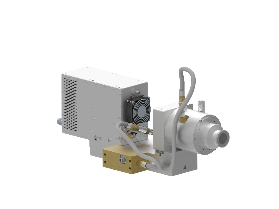
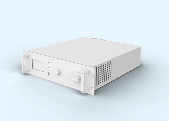
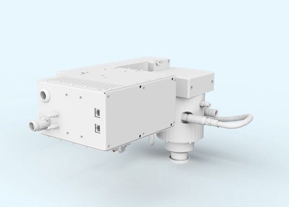
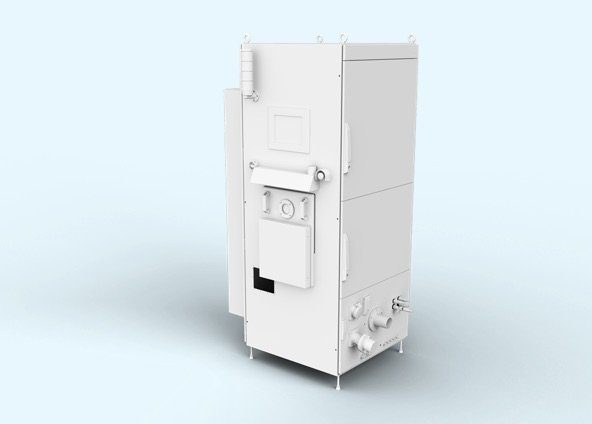
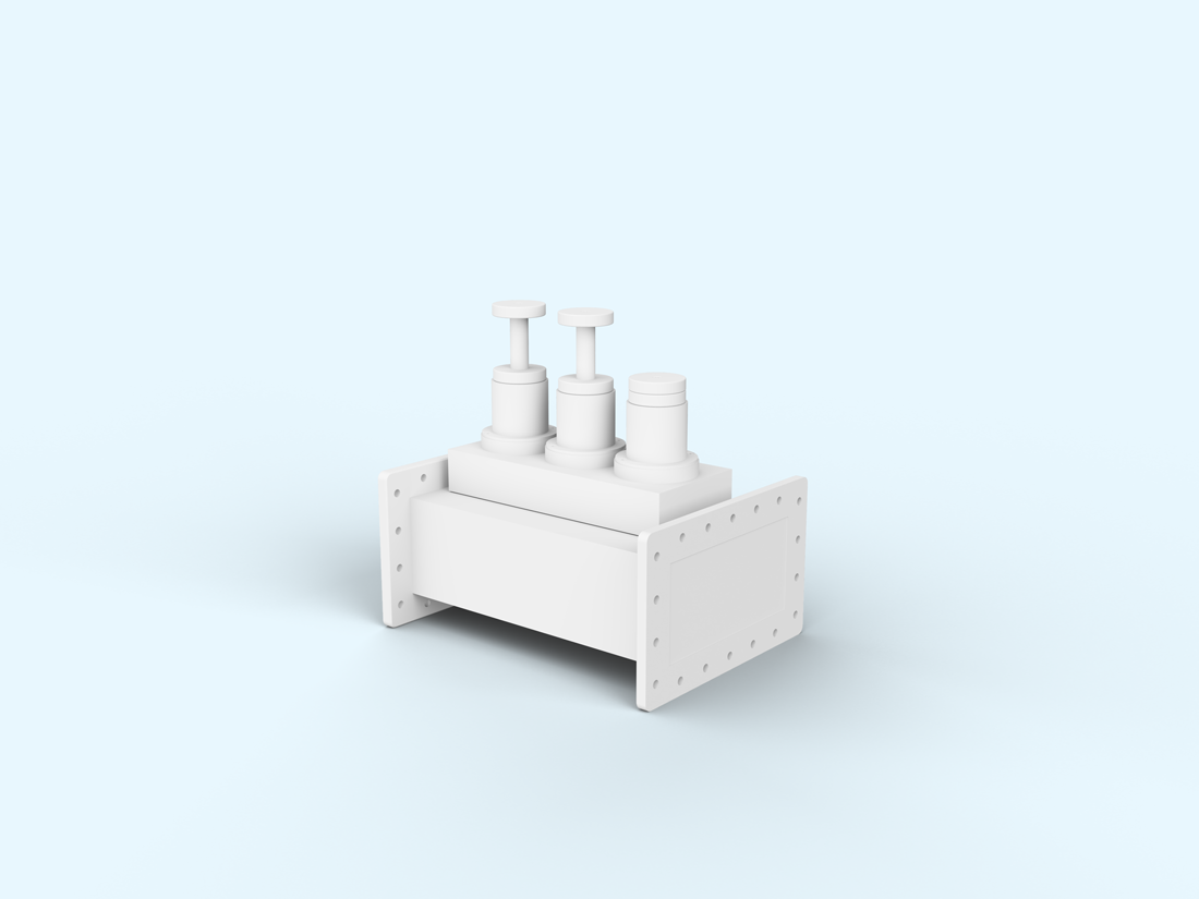
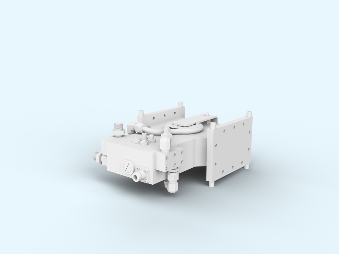
이러한 시스템의 예는 그림 2에 나와 있다. 구성요소의 특별한 순서(마그네트론, 커플링 스테이지, 순환기, 소스로의 전환, 플라즈마에 대한 출력)는 임피던스를 완벽하게 매칭시키므로, 거의 0에 가까운 반사전력 시스템이 보장된다.
그림 2: 소형 RPS("원격 플라즈마 소스")로서 설계에 완벽히 매칭됨. 대량 생산 환경의 경우, 유닛은 정확히 복제되며, 튜닝 없이 즉시 사용할 수 있다.
결론
반사전력은 모든 플라즈마 공정에서 관찰되는 공정 매개변수이다. 마이크로파 공정에서 반사전력의 존재는 RF(무선 주파수) 프로세스와 달리 상대적으로 중요하지 않은 매개변수이다. 공정 효율을 최적화하려면, 반사전력 값이 가능한 한 낮아야 한다.
RF 공정에 작은 반사가 있어도 원치 않는 방전(아크 발생) 또는 발생기의 파괴로 이어질 수 있다; 마이크로파 시스템에서는 반사전력이 공정 효율성을 나타내는 지표이다. 반사전력이 낮을수록, 공정에 사용할 수 있는 전력이 높아진다. 마이크로파 공정에서 반사전력은 아이솔레이터의 물 부하에 의해 흡수되고, 플라즈마 시스템의 어떤 부품도 위험하게 만들지 않는 상태에서 열(heat)로서 제거된다
Power-to-X ApplicationsDecontamination of Process Water containing Organic Residues using an Atmospheric Pressure Microwave Plasma Process
The thermo-catalytic reforming process (TCR® process) developed through a collaboration between MUEGGE and the Fraunhofer Institute for Environmental, Safety and Energy Technology (Fraunhofer UMSICHT) produces …
How plasma technology solves the challenge of performance degradation in fuel cells Fuel cells based on ionomer membranes are very important in applications such as …
How Duo-Plasmaline systems open new horizons for growing markets Solar power remains an almost inexhaustible reserve of energy on our scale, as well as being …
You are currently viewing a placeholder content from Google Maps. To access the actual content, click the button below. Please note that doing so will share data with third-party providers.