The reflected power is defined as the portion of the generated microwave power that is not coupled into the process and that returns back to the generator. In microwave processes this is an important parameter employed to assess the efficiency of the microwave energy transfer into the material(s) to be heated or into the plasma. This article describes what the reflected power value means, which parameters influence the reflection of the microwaves and how to minimize the reflected power.
One of the advantages of microwave plasma systems is that, unlike in RF (radio frequency) plasma systems, the reflected power does not cause any direct damage and can be used for process optimization.
Explanation of a microwave (-plasma) system
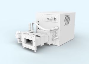
In the following example a classical microwave plasma system is described using the model of an atmospheric burner.
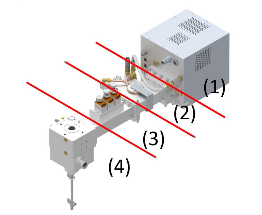
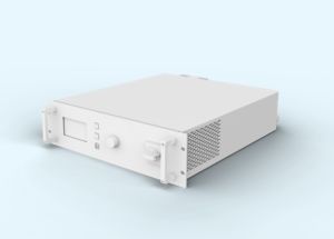
- The microwave generator driven by a high voltage power supply (usually a switching mode) produces microwave power via a magnetron; in the example of Figure 1, at 2.45 GHz frequency.
- The isolator is a two-port device that allows the microwave power to pass from the microwave generator to the load but not to return back to the magnetron/generator if reflected power is created. The most common use of such device is to protect the magnetron from the damaging effects that reflected power can have. At the entrance of the isolator, the reflected power – usually created by a poorly absorbing load – is diverted to and absorbed by a perfectly matched water load and dissipated as heat in the circulating water.
- The three-stub tuner is an optional component that allows for a wide process window of the system by matching the impedance of the magnetron to the impedance of the load (e.g. plasma). For very dynamic processes it is useful to run the tuner automatically. However, if a process undergoes little changes, i.e. is stable for microwave coupling, the impedances can be permanently matched from the beginning of the process. In this case the matching can be done via individual, fixed tuning elements.
- Load represented by an Atmospheric Plasma Source (APS)
Reflected power as a cause of impedance mismatch
Root cause
Reflected power always occurs when the components of the plasma system (i.e. microwave generator and plasma source) are not properly matched. In microwave processes this occurs due to changes of waveguide geometry, line geometry (coaxial conductor, stripline etc.), but also due to the change of the dielectric load in the process chamber. Thereby the microwave coupling can vary due to changes of the process material, evaporating water, plasma ignition, temperature, pressure etc., which requires an adjustment of the impedance matching in order to decrease the reflected power. The more abruptly these changes occur in the system, the more difficult it becomes to compensate for the mismatch with a single matching element.
All these effects can be explained by impedance matching and visualized by means of a Smith chart. The generator and the load can be assigned (frequency-dependent) complex impedances, which are matched by a complex matching network. The matching network is built by ideally resistive free inductors and capacitors. In the case of Figure 1, this corresponds to the three tuning stubs of the tuner, which can be lowered into the waveguide at different depths.
Significance for MW (microwave) processes
Due to the existence of the isolator as a protective element, the creation of reflected power does not represent a major issue for the hardware used in microwave applications: the reflected power is absorbed by the water load of the isolator and converted into heat even if the reflected power is 100 % of the power generated by the microwave generator. The reflected power is usually measured at the isolator level and as such, the operator can calculate how much power is absorbed by the load. In general, a microwave process should be operated at the lowest value of the reflected power in order to run the application with maximum energy efficiency.
Significance for RF (radio frequency) processes
Due to RF plasma operation at lower frequency by comparison to microwave frequencies (e.g., 13.56 MHz vs. 2.45 GHz), isolators are not available in RF plasma processes and the reflected power becomes critical. High reflected power in the RF process chamber can cause damage to components by unwanted arcing and in the worst case, the reflected power can destroy the generator.
Impedance matching
Manual/Automatic
For standard systems, various tuning elements can be used. Besides the already mentioned 3-stub tuner, plate (iris) tuners or E-H tuners can be used. The tuners can be operated manually or automatically to minimise the reflected power by changing the wave transmission behavior from the generator to the load as to optimize the matching.
Fixed Tuning
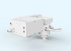
If a system is very well designed, the wave transmission properties can be predicted. In this case the geometry of the transition can be fixed and does not need additional adjustment and no moving elements will be required.
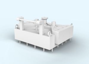
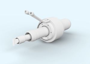
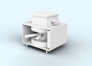
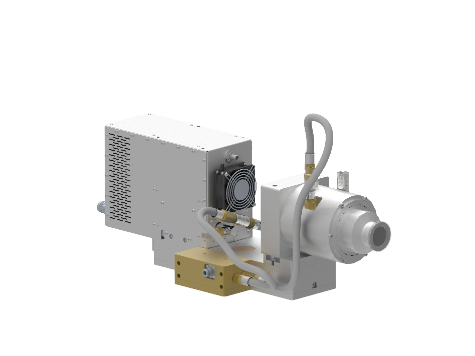
An example of such a system is shown in Figure 2. The special sequence of the components (magnetron, coupling stage, circulator, transition into the source, power output to the plasma) allows a perfect matching of the impedances, which ensures an almost zero reflected power system.
Conclusions
The reflected power is a process parameter observed in all plasma processes. In microwave processes the existence of the reflected power is, in contrast to RF (radio frequency) processes, a relatively uncritical parameter. The reflected power value should be as low as possible, to optimize the efficiency of the process.
Even small reflections in RF processes can lead to unwanted discharges (arcing) or even to destruction of the generator; in microwave systems the reflected power is a measure for the efficiency of the process. The lower the reflected power, the higher the power available to the process. In microwave processes the reflected power is absorbed by the isolator’s water load and eliminated as heat without endangering any parts of the plasma system.