MUEGGE provides solutions for breaking down the greenhouse gases CO2 and methane by atmospheric plasma.

Watch our explainer video and learn how our microwave assisted plasma technology can help combat climate change.

The unique properties of the Atmospheric Plasma Source (APS) can be used for applications formerly not available for plasma technology, like Power-to-X and related renewable energy technologies. Power-to-X using APS allows efficient ways to store surplus energy in form of hydrogen, ammonia or fuel.

The thermo-catalytic reforming process (TCR® process) developed through a collaboration between MUEGGE and the Fraunhofer Institute for Environmental, Safety and Energy Technology (Fraunhofer UMSICHT) produces synthetic natural gas, pyrolytic carbon, and synthetic crude oil. Process water is used in the TCR® process; after the process, the water is contaminated with organic compounds like acetonitrile, acetic acid, phenol, pyridine, and pyrroles. For the process water to be recycled, these organic compounds must be removed. MUEGGE’s atmospheric pressure microwave plasma torch [1] was applied for the decontamination of process water.

1. Atmospheric pressure microwave plasma setup for the decontamination of process water

The decontamination of the process water was performed by Fraunhofer UMSICHT using MUEGGE’s atmospheric pressure microwave plasma torch operated with air at 2.45 GHz, see Figure 1. The treatment process consists of swirling compressed air into the contaminated process water and to inject the resulted air-water flow via a venturi nozzle into the MUEGGE 2.45 GHz plasma torch as to form tiny droplets of water [2]. The smaller the droplets of process water in the pressurized airstream, the higher the probability for complete dissociation of the organic compounds in the high-energy microwave plasma. The desirable result of this atmospheric pressure plasma cleaning process would be the complete conversion of the organic compounds into water vapor and carbon dioxide after dissociation and reaction with hydroxide- and oxygen-radicals formed within the microwave plasma.

Figure 1: Atmospheric pressure microwave plasma setup for decontamination of process water.

At the exit of the 2.45 GHz air plasma, the decontaminated process water can be easily recaptured by rapid cooling, as shown in Figure 2.

Figure 2: Recapturing the decontaminated process water by quenching.

To demonstrate the efficiency of the atmospheric pressure microwave plasma decontamination of process water, solutions of 8.74 g ethanol and 16.81 g acetic acid dissolved in 1 l of distilled water were used as substitutes of the organic compounds in the laboratory scale experiments performed by Fraunhofer UMSICHT.

2. Results of the plasma decontamination tests using a solution of ethanol

A solution of 8.74 g of ethanol in 1 l of distilled water was injected in compressed air and fed into the atmospheric pressure microwave plasma with a flowrate of 130 l/min, which corresponds to a flowrate of approximately 65 ml/min of the test solution. According to the results obtained by Fraunhofer UMSICHT, the proportion of ethanol dissolved in distilled water was reduced by 92% after its treatment in the air microwave plasma using 2 kW of microwave power.

3. Results of the plasma decontamination tests using a solution of acetic acid

A test solution of 16.81 g of acetic acid in 1 l of distilled water was added into compressed air and fed into the atmospheric pressure microwave plasma with a flowrate of 130 l/min, which corresponds to a flowrate of approximately 65 ml/min of the test solution. Measurements of the content of acetic acid dissolved in distilled water showed a reduction by 88% after its treatment in the air microwave plasma operated at 2 kW of microwave power.

4. Conclusion: Successful and efficient decontamination of the process water by atmospheric pressure microwave plasma

The laboratory experimental results have shown 92% reduction of ethanol and 88% reduction of acetic acid using the atmospheric pressure air plasma at 2 kW microwave power.

These preliminary results are very promising for high efficiency cleaning of process water from TCR® applications. Working at elevated microwave power levels (e.g., MUEGGE’s 75 kW APS @ 915 MHz) will allow the removal of significantly higher quantities of organic contaminants and the process of considerably higher flows of contaminated process water.


References

[1]        Müller, Robert and Gorath, Moritz, et al.: Atmospheric Pressure Plasma Source and Downstream Source: Characteristics and Industrial Applications, Invited Talk, Contributions to 56th Annual Microwave Power Symposium (IMPI 56), Savannah, Georgia (USA), June 14-16, 2022.

[2]        Kaiser, Nadine: Behandlung von schwach kontaminierten Abwässern mittels Plasma-Technologie (Treatment of low-contaminated residual water using plasma technology), Bachelor’s Thesis, Technische Hochschule Nuremberg „Georg Simon Ohm“, August 4, 2021.

How plasma technology solves the challenge of performance degradation in fuel cells

Fuel cells based on ionomer membranes are very important in applications such as zero emissions vehicles. The major disadvantage of commercially available membranes, e.g., Nafion, in direct methanol fuel cells (DMFC) is their relatively large permeability for methanol, which leads to a drastic degradation of the efficiency of the fuel cell. Figure 8 shows the schematic of a DMFC. Plasma surface treatment of such membranes can reduce their permeability to methanol. In addition, the bond strength of the membrane to the catalyst can be significantly improved by plasma surface treatment.


Figure 1: Schematic of a direct methanol fuel cell (DMFC) [8-9].

1. Plasma technology to improve water management issues

The porous gas diffusion layer (GDL) is another important component of a fuel cell. It provides a homogeneous gas flow to the catalyst and controls the water content of the cell. In particular, the water management over a wide range of the voltage/current polarization curves is very important for the efficiency of the fuel cell. However, GDLs mostly consist of a strongly hydrophobic material which is critical for a proper water management. A partially hydrophilic GDL is a better choice because it can retain a certain amount of water in the fuel cell.


Figure 2: Completely hydrophobic surface of a gas diffusion layer (GDL) showing hydrophilic properties of the areas exposed to the microwave plasma (cf. water droplets adhered to these hydrophilic areas after low-pressure microwave plasma treatment) [9-10].


Partially hydrophilic properties of the GDL can be achieved by e.g., surface treatment of the GDL in a nitrogen plasma process. When the GDL is covered by a perforated plate, only the uncovered areas of the surface of the GDL will be modified in the plasma process. Consequently, the uncovered areas of the surface of the GDL show hydrophilic properties after plasma treatment (water droplets adhering to these areas – Figure 2), whereas the covered areas of the surface of the GDL retain their initial hydrophilic properties.

2. Proven results: Fuel cells show higher performance

The fuel cells with plasma treated GDL show significantly higher cell voltages than the reference fuel cells without plasma treated GDL. This is due to the fact that the membrane of a fuel cell without plasma treated GDL runs dry, especially at higher current densities. When using a plasma treated GDL, a certain amount of water can be retained in the cell leading to a better fuel cell performance.

Plasma technology can boost your performance in many ways. Contact us to find out how we can customize or standardize our systems for your challenges – let us help to fuel your innovations, too.


References

[1]          M. Walker, K.-M. Baumgärtner, M. Kaiser, J. Kerres, A. Ullrich, E. Räuchle, J. Appl. Polym. Sci., 1999, 74, 67-73.

[2]          M. Walker: Fuel Cells. [online] Homepage: University of Stuttgart, Institute of Interfacial Process Engineering and Plasma Technology (IGVP)

URL: https://www.igvp.uni-stuttgart.de/en/research/plasma-technology/processes/fuel-cells/ [status: June 16, 2021].

How Duo-Plasmaline systems open new horizons for growing markets

Solar power remains an almost inexhaustible reserve of energy on our scale, as well as being geographically accessible, despite its intermittence. However, photovoltaic production has always had its limits. There is still room for improvement when it comes to reflection qualities of the surface coating and more economical ways of producing solar panels. Additionally, our age of fast-paced innovation demands for photovoltaic design for applications never imagined before. Due to its unique performance in surface treatment, Duo-Plasmaline is the revolutionary technology if you want your innovation to work more efficiently than ever. The three main reasons why are:

1. Reason One: Optimization of the reflection behavior

The effectiveness of light conversion into energy of silicon solar cells is linked to the minimization of reflection losses and surface recombination. Thin plasma-polymerized SiN films are used to improve both properties i.e., the reflection behavior by adjusting the refractive index of the anti-reflection coating and the surface properties to avoid recombination at the surface.


Muegge’s Duo-Plasmaline technology acts superior in creating a homogeneous plasma. Combined with a Plasma Array, it is suitable for continuous and batch processes. Both Duo-Plasmaline and Plasma Array provide highly efficient surface treatment of even thermally sensitive materials due to high radical densities at lowest ion energy of the non-equilibrium microwave plasma at low-pressure.


Figure 1: Plasma array consisting of six Duo-Plasmalines integrated into a process chamber for e.g., low-pressure plasma deposition of thin films used in the production of solar cells (courtesy of Meyer Burger Germany)


These properties are critical for SiN films used in photovoltaics: hardness and chemical resistivity are crucial properties of these layers. For this reason, SiN can be applied both as an insulator and as barrier-material for many industrial applications.

“This highly stable plasma process really opens doors for a more economic production, but also for a whole new set of possibilities in designing photovoltaic applications for growing markets.”

2. Reason Two: Making your large-scale production more profitable

Photovoltaic devices will be more profitable if their price can be significantly reduced, e.g., by large-scale production. Thin film solar cells are of particular interest in large-scale production. Glass plates are state-of-the-art substrates for thin film solar modules made of e.g., copper-indium-gallium di-selenide (CIGS). They can be replaced by thin metal foils to reduce both weight and material costs. The heavy glass substrate and the glass covering can be substituted by a systems of thin polymer films deposited in a low-pressure microwave plasma process on the metal plate and on the optical layers on top of the CIGS solar modules.

3. Reason Three: Entering new markets with more flexibility

Standard CIGS solar modules consist of monolithically connected solar cells. Therefore, the metal foil has to be insulated. In addition, diffusion of material impurities and contamination from the metal foil into the CIGS must be prevented by a diffusion barrier. The advantage of using thin metal foils as substrate material is the flexibility of the modules which makes them suitable for mobile applications and wearables.

Figure 2: Monolithically connected copper-indium-gallium di-selenide (CIGS) solar modules on a flexible metal foil with a plasma-deposited diffusion layer in between [5-7].

4. Beyond limits: Plasma process empowering your innovations

Plasma processes for deposition of thin polymer films acting as diffusion barriers enable new technologies for economical production of flexible photovoltaic modules. Furthermore, plasma processes can be used for deposition of thin film amorphous silicon (a-Si) solar cells and for microcrystalline silicon (µc-Si) solar cells, thus introducing important new markets for plasma technology.


Want to know how our plasma systems can help your ideas grow into new products and new markets?
 
Contact us and we will bring power to your projects.
 

References

[1]          H. Schlemm, A. Mai, S. Roth, D. Roth, K.-M. Baumgärtner, H. Mügge, Surf. Coat. Technol., 2003, 174-175, 208-211.


[2]          M. Troia, M. Walker: Diffusion Barrier Layers. [online] Homepage: University of Stuttgart, Institute of Interfacial Process Engineering and Plasma Technology (IGVP)

URL: https://www.igvp.uni-stuttgart.de/en/research/plasma-technology/processes/diffusion-barrier-layers/ [status: June 16, 2021].

How innovative plasma systems bring silicon anodes into lithium-ion battery applications

In 2007 researchers at Stanford University discovered a solution to the challenges associated with the use of silicon in batteries. They were able to store lithium in tiny silicon nanowires by using new nanotechnology techniques and methods. The dimensions of these silicon nanowires are about one thousand times thinner than the thickness of a sheet of paper. The silicon nanowires swell when they absorb positively charged lithium ions, while their physical properties i.e., size and shape, inhibit the silicon from fracturing and breaking apart.

1. Silicon anodes boosting - Performance of lithium-ion batteries

For the reasons mentioned above, silicon is widely considered to be the future material of choice in anode technology. Battery-builders and automakers want to take advantage of its high theoretical charge capacity. It has been proven that batteries with silicon anodes achieve significantly higher energy per unit volume and per unit weight than today’s commercially available batteries based on carbon-anode designs.


Figure 5: Three-dimensional growth of silicon columns by low-pressure microwave plasma deposition for pure silicon anodes [3].

Manufacturing facilities relying on Duo-Plasmaline technology for plasma enhanced chemical vapor deposition (PECVD) of three-dimensional porous silicon layers have high potential for producing silicon nanowire anodes. Figure 5 shows silicon columns three-dimensionally grown by low-pressure microwave plasma deposition for pure silicon anodes.

2. Duo-Plasmaline enabling homogeneous and sensitive surface treatment

The combination of Duo-Plasmaline and Plasma Array provides highly efficient surface treatment of even thermally sensitive materials due to high radical densities at low ion energy of the non-equilibrium microwave plasma at low-pressure. The plasma is formed by microwave excitation only, i.e. without the effect of an additional magnetic field. This allows to easily upscale applications for large batches that need a highly precise and homogeneous surface treatment and for materials that require very sensitive processing.


Interested? Would you like to discover how this technology works in detail? Read our in-depth article about Duo-Plasmaline technology. (Link to Article 1)


Should you like know more about how Duo-Plasmaline may benefit your product portfolio and how MUEGGE can customize this technology for you, do not hesitate to contact us.


References:

[3]          Applying Solar Technology for Pure Silicon Anodes: Porous Silicon Anodes. [online] Homepage: LeydenJar Energising Technologies, URL: https://leyden-jar.com/technology/ [status: June 16, 2021].

How Duo-Plasmaline systems bring power to your sustainable energy applications

Everybody wants to live on a healthier planet! Innovators from all industries are working hard towards a more sustainable future. Yet in many cases, there is still room for improvement with regards to the efficiency, quality and upscalability of green technologies, especially of those linked to the manufacturing of zero emission car batteries and flexible photovoltaic panels.


MUEGGE’s microwave-powered Duo-Plasmaline systems allow innovators to step up their game when it comes to surface processing and modification in the field of sustainable energy production and storage.

If you want to understand the hows and whys of this technology, this expert review will help you to discover how Duo-Plasmaline systems enable high radical densities, high plasma homogeneity on large treated areas, and easy upscaling.


1. Generating homogenous plasma: Where other systems fail to perform

Microwave plasma excitation at low-pressure is based on the acceleration of free electrons within the electric field of the microwaves. Ideally, once formed via gas ionization, the electrons collide with each other and with neutral and charged species producing an avalanche effect which leads to the formation of the plasma. The operating pressure of the vacuum chamber is an important parameter in this process: at low-pressure the mean free path of the accelerated free electrons is significantly shorter than the dimensions of the vacuum chamber and a non-equilibrium plasma is formed, characterized by neutrals and ions at ambient temperature and by “hot” accelerated free electrons. When the pressure in the vacuum chamber is further reduced so that the mean free path of the free electrons is in the range of the dimensions of the vacuum chamber, the probability of collision between the free electrons with the walls of the vacuum chamber increases significantly, thus inhibiting the avalanche effect which is essential for forming and sustaining the plasma.

“Reducing or increasing the pressure the wrong way may inhibit forming or sustaining a plasma.”

On the other hand, increasing the pressure will allow the energy transfer to heavy particles like neutrals and ions, causing the plasma to gradually thermalize. Therefore, the bulk temperature of the plasma increases. On the other hand, if keeping the microwave energy constant by increasing the particle density, e.g., by increasing gas flow, the excitation energy will not be sufficient to maintain the plasma.


Increasing the electron density at constant pressure inhibits microwave propagation. At the so-called critical density, microwaves can no longer penetrate the plasma and are reflected, the plasma acting like a conducting wall.


N.B. The critical density is proportional to the square of the frequency of the electromagnetic wave.


2. For enhanced productivity and easy upscaling - Duo-Plasmaline is the solution

Based on the principles underlined above, many microwave plasma sources have been conceived as to take advantage of the elevated efficiency of the high radical density that is typical to microwave plasmas. However, the formation of specific modes, of standing waves and the fact that the vacuum wavelength of the microwaves can have the same geometrical dimension as the material to be treated can lead to inhomogeneous plasma treatment of the substrate’s surface. Scaling-up microwave plasma sources for large substrates is an important challenge. The Duo-Plasmaline microwave plasma source as well as the Plasma Array (based on multiple Duo-Plasmaline) perfectly measure up to these challenges.


3. Increasing your product quality - Duo-Plasmaline for homogeneous plasma

The Duo-Plasmaline is a low-pressure microwave plasma source. The plasma is formed by microwave excitation only i.e., without the effect of an additional magnetic field. To put it simply, the Duo-Plasmaline is an inverse fluorescent tube excited by microwaves: a coaxial line is mounted through the vacuum vessel i.e., the microwave energy transmission line (antenna) made of electrically conducting material and powered by microwaves from both sides. Inside the vacuum vessel, the outer coaxial conductor is replaced by a dielectric tube made of glass, quartz or ceramics. The inside of the dielectric tube is at atmospheric pressure, whereas the outside i.e., the vacuum vessel, is at low pressure, preferably in the range between 10 Pa and 1000 Pa. Microwaves can pass the dielectric tube and propagate into the low-pressure regime of the vacuum vessel. When the electric field strength of the microwaves exceeds the breakdown field strength, a discharge ignites in the low-pressure regime at both ends of the Duo-Plasmaline where the outer coaxial conductor is replaced by the dielectric tube. The short plasma ‘hoses’ formed at both ends of the Duo-Plasmaline are electrically conducting media and thus replace the missing outer coaxial conductor. With the increase of the microwave power, the plasma extends from both ends along the dielectric tube, until an axially homogeneous plasma is formed – see Figure 1.


Figure 1: Axially homogeneous plasma formed around the Duo-Plasmaline low-pressure microwave plasma source [1]


The formation of an axially homogeneous low-pressure plasma around a Duo-Plasmaline with a length of over 3 m has been demonstrated for applications using only a few kW of 2.45 GHz microwave power.


4. Combining powers - Duo Plasmaline and Plasma Array for highly efficient surface treatment

A two-dimensional Plasma Array source is obtained when arranging equidistantly two or more parallel Duo-Plasmalines. While a Duo-Plasmaline provides an axially homogeneous plasma, the Plasma Array generates a large and homogeneous plasma, see Figure 2. Consequently, a Duo-Plasmaline is preferably used for plasma surface treatment in continuous in-line processes, whereas a Plasma Array is suitable for continuous and batch processes. Both the Duo-Plasmaline and the Plasma Array allow highly efficient surface treatment even for thermally sensitive materials because of the high radical density at low ion energy of the non-equilibrium microwave plasma at low-pressure.


Figure 2: Two-dimensional homogeneous plasma formed by a Plasma Array microwave plasma source at low-pressure [2].


5. Customize your surface dimensions - Scalability of plasma area in width and length

Due to its modular design, the Plasma Array is easy to adapt to the dimensions of the substrate by configuring the number and the length of the Duo-Plasmalines in the Plasma Array. Hence, the active plasma area can be scaled in width and length.


Figure 3: Schematic of a Plasma Array consisting of four Duo-Plasmalines for low-pressure plasma treatment of a surface (represented in green)

A schematic of a Plasma Array consisting of four Duo-Plasmalines in a process chamber for plasma surface treatment at low-pressure is shown in Figure 3. The four Duo-Plasmalines are supplied with microwave energy from the left and from the right. The microwave energy is generated by two magnetron-heads on each side. Each magnetron-head supplies two Duo-Plasmalines with microwave energy via a power splitter. Power split equally to two or more Duo-Plasmalines guarantees the best plasma homogeneity on the substrate. 


Figure 4 shows a Plasma Array consisting of six Duo-Plasmalines with a length of 160 cm each, thus forming an active plasma area of approximately 150 cm x 200 cm for e.g., coating of solar cells with silicon-nitride.


Figure 4: Plasma array consisting of six Duo-Plasmalines integrated into a process chamber for e.g., low-pressure plasma deposition of thin films used in the production of solar cells (courtesy of Meyer Burger Germany)


6. Open possibilities for innovative applications - Duo-Plasmalines and plasma arrays

Apart from deposition of thin films, Muegge’s Duo-Plasmalines and Plasma Arrays sources are also used for plasma assisted surface treatment like surface activation, etching, cleaning and even sterilization. Today and going forward, this exciting technology offers a broad range of revolutionary processes for sustainable energy production and storage. Examples of exciting applications for non-equilibrium microwave plasma processes at low-pressure include the deposition of silicon nanowires for novel lithium-ion batteries and surface modifications in fuel cell technology.


Visit our website to discover our hands-on cases and examples of Duo-Plasmaline and Plasma Arrary and to find out how you can use them to support your innovations and product development.


References

[1]          A. Schulz, P. Büchele, E. Ramisch, O. Janzen, F. Jimenez, C. Kamm, J. Kopecki, M. Leins, S. Merli, H. Petto, F. R. Mendez, J. Schneider, U. Schumacher, M. Walker, U. Stroth, Contrib. Plasma Phys., 2012, 52, 607-614.

[2]          M. Walker, A. Schulz: Duo-Plasmaline. [online] Homepage: University of Stuttgart, Institute of Interfacial Process Engineering and Plasma Technology (IGVP)

URL: https://www.igvp.uni-stuttgart.de/en/research/plasma-technology/sources/plasmaline/ [status: June 16, 2021].

Gesundheit, Fitness, Ernährung und Umwelt, beschäftigt unsere Gesellschaft, quer durch die Generationen, mehr denn je zu vor.


Passt die Mikrowelle in diese Welt der guten Trends?


Fast jeder Haushalt hat einen Mikrowellenherd. Der Komfort, ist unbestreitbar. Doch trotz der weiten Verbreitung von Mikrowellenherden und ihrer ausgezeichneten Sicherheitsbilanz polarisiert die Mikrowelle noch immer und manche glauben, dass die Zubereitung von Speisen mit Mikrowelle irgendwie ungesund ist, weil die Nährstoffe aus den Lebensmitteln verloren gehen könnten.


Ist das Kochen mit Mikrowellen wirklich ungesund?


Wir klären auf.


Das erwartet Dich hier

  1.   Wie funktioniert Mikrowelle eigentlich?

  2.   Ist das Kochen von Lebensmitteln in der Mikrowelle schädlich?

  3.   Wie verändern sich die Vitamine in der Mikrowelle?

  4.   Industrielle Anwendungen von Mikrowellen

  5.   Exkurs: Elektromagnetische Wellen

  6.   Digital cooking happens – die Digitalisierung des Kochens

  7.   Kontakt

1. Wie funktioniert Mikrowelle eigentlich?

Mikrowellen bekommen ihren Namen von der Mikrowellenstrahlung, einer hochfrequenten elektromagnetischen Strahlung, durch die das Essen erwärmt wird. Die Mikrowellen regen vor allem die Wassermoleküle zur Bewegung an und durch die Reibungsenergie wird das Essen erwärmt. Die Speisen selbst erfahren dadurch keine Strahlung, die Wirkung ist thermischer Natur.


Durch das Metallgehäuse eines Mikrowellenherdes bleiben die Strahlen im Gerät, so dass außerhalb, wenn überhaupt, nur extrem geringe Leckstrahlung messbar ist. Die erlaubten Grenzwerte werden streng eingehalten und die Geräte und deren Anwendung sind völlig ungefährlich.


Die Strahlungsfrequenz wird auch im Mobilfunk und für WLAN verwendet, dort aber bei sehr viel geringerer Leistung.


WICHTIG: Es gibt keinerlei Beweise dafür, dass die Mikrowelle schädlich beziehungsweise gesundheits­gefährdend ist, solange die Sicherheitsmaßnahmen eingehalten werden.


Mikrowellenherde erzeugen elektromagnetische Strahlung.


Sie finden das vielleicht beunruhigend, weil der Begriff „Strahlung“ häufig negativ belegt ist. Es handelt sich jedoch nicht um die Art von Strahlung, die mit nuklearen Katastrophen oder Waffen in Verbindung gebracht wird.

Mikrowellenherde erzeugen nicht-ionisierende Strahlung, die der Strahlung Ihres Mobiltelefons ähnlich ist – allerdings um einiges stärker.


Denken Sie daran, dass auch das sichtbare Licht eine elektromagnetische Strahlung ist. Ohne Licht gäbe es kein Leben, also kann nicht jede Strahlung schlecht sein.


MERKE: Mikrowellen erhitzen Lebensmittel auf Molekularebene. Mikrowellen werden als nicht-ionisierende Strahlung klassifiziert. Sie haben keine „radioaktive“ Wirkung auf Stoffe, biologische Gewebe und Lebensmittel.


2. Ist das Kochen von Lebensmitteln in der Mikrowelle schädlich?

Durch jede Garmethode werden einige Nährstoffe in Lebensmitteln verändert, so auch bei der Mikrowelle. Wie stark sich der Gehalt verändert, hängt von der Kochdauer und der Temperatur sowie der Menge des hinzugefügten Wassers ab.


Der Mikrowellenofen ist bei vielen verpönt und gilt als schädlich, ungesund und als ein Gerät, das jegliche Vitamine und Nährstoffe im Essen zerstört. Obwohl diese Aussage auch für jede andere Kochmethode gilt, setzt sich niemand so kritsch damit auseinander als für die Mikrowelle.


Viele Studien haben sich mit dieser Thematik beschäftigt. Einen klaren Nachweis, dass die Mikrowelle schädlich ist, gibt es jedoch nicht, ganz im Gegenteil. Studien weisen höhere Werte für Vitamine und Nährstoffe dem Garprozess mit der Mikrowelle zu.


MERKE: Es gibt keinen einzigen, nachprüfbaren Beweis, dass mit Mikrowellen gekochte Nahrungsmittel eine schädliche Wirkung auf Menschen haben oder das Lebensmittel selbst verändern. Lebensmittel aus der Mikrowelle sind nicht gesundheitsschädlich.


3. Wie verändern sich die Vitamine in der Mikrowelle?

Grundsätzlich hat die Erhitzung von Gemüse, Milch oder anderen Lebensmittel in der Mikrowelle keinen Einfluss auf deren Inhaltsstoffe. Zahlreiche Untersuchungen haben gezeigt, dass es – wie bei der konventionellen Zubereitung auf dem Herd – darauf ankommt, ob schonend gegart wird. Gemüse, das in normalen Portionen und mit sehr wenig Flüssigkeit in der Mikrowelle gegart wird, hat nicht weniger Vitamine als Gemüse, das auf dem Herd gedünstet wird. Die Faktoren Temperatur und Zeit sind entscheidend, um auf den Nährstoffgehalt Einfluss zu nehmen.


Hitzeempfindliche und wasserlösliche Vitamine wie Vitamin C oder B1 profitieren regelrecht von einer kurzen und schonenden Zubereitung mit wenig Wasserzugabe, da sie beim Kochen nach und nach ins Wasser übergehen. Wird die Flüssigkeit abgegossen, verschwinden sie im Abguss.


Beim Auftauen von Tiefgefrorenem kann die Mikrowelle einen weiteren Vorteil ausspielen, weil es möglich ist, die Auftauzeit deutlich zu verkürzen. Gleiches gilt, wenn in einer Familie jeder zu anderen Zeiten essen möchte und jeweils nur die eigene Portion in der Mikrowelle erwärmt. Da geht es nicht nur um Inhaltsstoffe, die bewahrt werden, sondern auch um Energie, die eingespart wird. 


Wenn die Mikrowelle richtig verwendet wird und der Benutzer darauf achtet, dass die Lebensmittel nicht heißer oder länger erhitzt werden als nötig, ist die schnelle Erwärmung deutlich nährstoffschonender als im Topf auf dem Herd. Während beim Kochen viele Vitamine ins Kochwasser gehen und anschließend weggeschüttet werden, ist in der Mikrowelle extrem wenig Wasser notwendig, um schonend zu garen. Es bleiben auch keine Mikrowellenstrahlung in der Nahrung zurück. Die Zusammensetzung des Essens wird also nicht verändert!


MERKE: Alle Garmethoden verringern den Nährstoffgehalt, aber die Mikrowelle bewahrt die Nährstoffe im Allgemeinen besser als andere Methoden. Weniger Garzeit und geringere Temperaturen unterstützen den Trend zu gesünderem Essen.


4. Industrielle Anwendungen von Mikrowellen

Das Vorgaren und Rösten von Speck ist eine der häufigsten Anwendungen der industriellen Mikrowellenverarbeitung. Viele Fastfood-Restaurants sind kommerzielle Nutzer dieser Technologie.


Die Mikrowellentrocknung ist sehr effizient und wird kommerziell für Snacks, Gewürze und andere Zutaten eingesetzt. Sie wird auch zur Fertigstellung trockener Nudeln und Instantnudeln verwendet. Der Einsatz von Mikrowellen im Bereich Vor- oder Nachtrocknen kann vorhandene Produktionskapazitäten deutlich steigern.


Eine häufige Anwendung von Mikrowellen in der Lebensmittelverarbeitung ist das Temperieren. Mikrowellen erzeugen schnell und volumetrisch Wärme, und das Auftauen erfolgt in Minuten statt in Stunden/Tagen, selbst bei großen Produktblöcken. Die Temperierung kann auch direkt in der Verpackung erfolgen. Die Mikrowellenerwärmung wird häufig zum Temperieren von tiefgefrorenem Rind- und Schweinefleisch, Geflügel und Fisch eingesetzt.


Herkömmliche Verfahren zur Sterilisation oder Pasteurisierung, wie das Retortenverfahren, werden im Allgemeinen durch drastische Wärmebehandlungen durchgeführt, was zu einem Verlust der Produktqualität führt. Die Mikrowellensterilisation oder Pasteurisation bietet das Potenzial kürzerer Prozesszeiten und verbesserter Qualität. Mit Mikrowellen prozessierte verpackte Produkte sind in Supermärkten kommerziell erhältlich. Dazu gehören komplette Fertiggerichte und Komponenten, wie Soßen, und Beilagen, die wir als Verbraucher in zunehmendem Umfang kaufen. Die Welt der reinen Genüsse erleben wir hier grenzenlos. Egal ob Mediterran, Asia und gut bürgerliche Küche, Bio oder Vegan, nur um einige Beispiele zu nennen – die Qualität ist eher mit frisch zubereiteten Speisen als herkömmlichen Fertiggerichten zu vergleichen.


Previous slide
Next slide

5. Exkurs: Elektromagnetische Wellen

Elektromagnetische Wellen sind im elektromagnetischen Spektrum nach der Wellenlänge eingeteilt.


Das sichtbare Licht stellt nur einen geringen Teil des gesamten Spektrums dar und ist, mit Ausnahme der Infrarotstrahlung (Wärme), der einzige Bereich, der von Menschen ohne technische Hilfsmittel wahrgenommen werden kann. Bei niedrigeren Frequenzen, wie zum Beispiel der Mikrowelle, ist die Energie der Photonen zu gering, um chemische Prozesse auslösen zu können.


Bei höheren Frequenzen hingegen beginnt der Bereich der ionisierenden Strahlung (Radioaktivität), bei der ein einziges Photon Moleküle zerstören kann. Dieser Effekt tritt bereits bei Ultraviolett-Strahlung auf und ist für die Bildung von Hautkrebs bei übermäßiger Sonnenexposition verantwortlich.


Mikrowellen ist ein Trivialname für elektromagnetische Wellen mit einer Frequenz von 1 bis 300 GHz, was einer Wellenlänge von ca. 30 cm bis 1 mm entspricht. Der Frequenzbereich der Mikrowellen umfasst also Teile des Dezimeterwellenbereiches sowie den Zentimeter- und Milli­meter­wellenbereich.


Aufgrund ihrer Wellenlänge sind Mikrowellen besonders zum Anregen von Dipol- und Multipolschwingungen von Molekülen geeignet. Besonders anschaulich ist dieser Effekt bei der Schwingungsanregung von Wassermolekülen im Mikrowellenherd. Die Erwärmung von Wasser beruht nicht auf der Absorption bei einer bestimmten Resonanzfrequenz, sondern die Wassermoleküle richten sich als Dipole ständig nach dem elektromagnetischen Wechselfeld aus, wobei als dielektrischer Verlust Wärme entsteht. Die in Mikrowellenherden verwendete Frequenz liegt bei 2,45 GHz. Damit erzielt man einen guten Kompromiss zwischen Absorption und Eindringtiefe in das Gargut.


Der dielektrische Verlustfaktor, der spezifische elektrische Widerstand sowie magnetische Verluste bestimmen die frequenzabhängige Absorption der Mikrowellen an oder in Stoffen, wie zum Beispiel Nahrungsmitteln, und somit deren Erwärmung.


6. Digital cooking happens – die Digitalisierung des Kochens

Auch wenn es immer noch ein besonderes Erlebnis ist, zusammen mit der Familie zu kochen, der Alltag sieht anders aus. Niemand nimmt sich noch Zeit, in der Küche zu stehen. Alles muss schnell passieren, auch das Kochen. Damit ändert sich aber auch die Erwartungshaltung an den Kochprozess selber – wir wollen keine Zeit vergeuden und erwarten dabei beste Qualität. Um das zu erreichen, müssen wir den Kochprozess revolutionieren. Digitalisierung ist auch hier das Zauberwort.


1 und 0, sind zwei Ziffern hinter denen ON und OFF steht, wenn wir Prozesse digitalisieren.


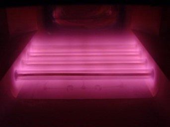
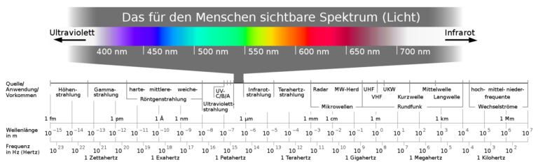
Die Quelle der Mikrowelle ist Strom und sie wirkt direkt im Produkt, das erhitzt werden soll.


Strom können wir sehr genau steuern und damit auch die Leistungsabgabe der Mikrowelle.


1 und ON steht für einen mit einem Computer genau steuerbaren Prozess, den wir z.B. Garen nennen. Während 0 und Off genauso exakt den Energieeintrag und seine Wirkung beenden.


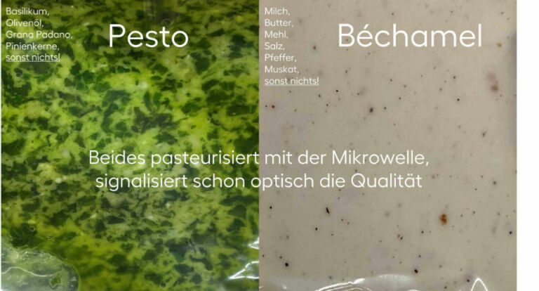
Das macht die Mikrowelle zur einzigen Methode, mit der Prozesse zur Erhitzung von Lebensmitteln 1:1 digital betrieben werden können. Andere ebenso etablierte Prozesse scheitern an dieser Digitalisierungsgrenze.


Das schließt alle Daten der gesamten Prozesskette ein und verbindet das Thema Food in enormem Umfang auch via Internet (AI/IOT). Es resultiert eine zu erwartende massive Skalierung in Vielfalt und Anzahl neuer Anwendungen, in Techniken, Maschinen, Hard & Software. Die Daten daraus sind direkt verbunden und fließen direkt in die Verbesserung des digitalen Konzeptes.


Dazu kommt ein neuer Anspruch seitens Energie und Umwelt und wie wir damit umgehen. Es liegt auf der Hand, dass Einsparung und Optimierung sehr stark mit Digitalisierung einhergehen. Hier passiert sehr viel und vor allem schnell, insbesondere wenn Strom die Energiequelle ist.


Wie direkt Anwendungen und Produkte mit der Welt der Daten verbunden sind, spielt auch eine große Rolle. Elektromobilität, Licht, Wärme und Kommunikation sind gute Beispiele, die Orientierung bieten.


Damit zählt die Mikrowelle zu den Schlüsseltechnologien unserer Gesellschaft, um neue Wege zu gehen. Seit der Mensch das Feuer kennt, wartet das inzwischen angesammelte Wissen darauf, neu mit der Welt der reinen Genüsse verbunden zu werden.


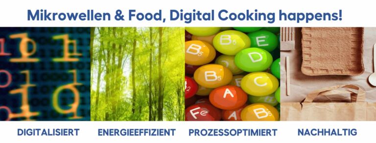
Digital cooking happens!


7. Kontakt

Haben Sie Fragen?


Brauchen Sie Unterstützung für die Umsetzung Ihrer Anwendung?


Melden Sie sich! Wir beraten Sie gerne!


POWER TO YOUR PROJECTS!


Reichelsheim, Germany
Tel.: +49 (0) 6164 - 9307 - 0
Fax: +49 (0) 6164 - 9307 - 93
info@muegge.de
www.muegge.de
Modesto, CA 95351, USA
Phone: +1-(209)-527-8960
Fax: +1-(209)-527-5385
sales@muegge-gerling.com
www.muegge-gerling.com

Kunden, die sich für industrielle Mikrowellensysteme interessieren, wissen verständlicherweise nicht genau, wie viel Energie sie für ihre spezielle Anwendung benötigen. Je nachdem, ob es um Garprozesse, das Temperieren von Tiefkühlprodukten oder das Trocknen von Materialien geht – der Energiebedarf ist je nach Material und Anwendung sehr unterschiedlich.


In diesem Beitrag konzentrieren wir uns auf eine häufige Anwendung: das Verdampfen von Wasser.

Wir haben eine Zusammenfassung des allgemeinen Prozesses und der Berechnungen zusammengestellt, die zur Bestimmung der für die Trocknung Ihres Materials erforderlichen Energiemenge notwendig sind.


Die Mikrowellentrocknung ist schneller und häufig energieeffizienter als herkömmliche Methoden wie Trockenräume und Konvektionsöfen. Nutzen Sie diese Informationen, um die langfristigen Betriebskosten im Zusammenhang mit der Trocknung mit Mikrowellenenergie zu ermitteln.

Das erwartet Dich hier

Energieabschätzung zur Trocknung mit Mikrowellen 

  1.   Bestimmung der zu verdampfenden Wassermenge

  2.   Bestimmung, wie Ihr Material auf Mikrowellen reagiert

  3.   Berechnung des Energiebedarfs

  4.   Sprechen Sie mit uns

  5.   Kontakt

1. Bestimmung der zu verdampfenden Wassermenge

Bei jedem beliebigen Material müssen Sie zunächst feststellen, wie viel Wasser es vor dem Trocknen enthält. Zudem müssen Sie einen Zielwert für den Wassergehalt nach dem Trocknungsprozess festlegen.


Wenn Sie zum Beispiel 100 Kilogramm Material mit einem Wassergehalt von 60 % haben, das Sie auf 10 % Sättigung bringen müssen, lautet die Berechnung einfach:


Zu verdampfende Menge Wasser [kg] = 100 kg *(0,6 – 0,1) = 50 kg


Im Allgemeinen geben Sie auch eine Trocknungszeit vor, in der Sie das Material den Mikrowellen aussetzen wollen, um dieses Ziel zu erreichen.

2. Bestimmung, wie Ihr Material auf Mikrowellen reagiert

Häufig ist Wasser das mikrowellenaktivste Molekül in dem feuchten Grundmaterial und absorbiert durch seine hohen dielektrischen Verluste den Hauptteil der eigespeisten Energie. Daher ist die Energiemenge, die durch Absorption an den Rest des zu trocknenden Materials verloren geht minimiert.


Die folgenden Berechnungen beziehen sich auf die Energiemenge, die erforderlich ist, um das Wasser allein zu verdampfen, und sollten daher als grobe Schätzung der einzusetzenden Gesamtenergie dienen, die Sie benötigen werden, da ein geringer Teil der Energie für die Erwärmung des restlichen Materials benötigt wird.


Dieser Verlust ist häufig gering. Bei einem Grundmaterial mit einem hohen dielektrischen Verlust kann die Mikrowellenabsorption des Nicht-Wasseranteils allerdings nennenswert werden.  Wenn Sie ein solches Material in der Mikrowelle prozessieren wollen, sollten Sie eine längere Trocknungszeit einplanen, um eine zu starke Erwärmung des Grundmaterials zu vermeiden.

3. Berechnung des Energiebedarfs

Für eine Beispielrechnung nehmen wir nun einmal an, dass wir 50 kg Wasser in einer Stunde verdampfen wollen. Weiterhin nehmen wir an, dass die Ausgangstemperatur des Materials Zimmertemperatur, also 20°C, beträgt.

Die Formel zur Berechnung der Energiemenge, die zum Verdampfen von Wasser erforderlich ist, basiert auf der spezifischen Wärmekapazität von Wasser:


Es ist eine Energie von 4,19 Kilojoule (kJ) erforderlich, um ein Kilogramm Wasser um ein Grad Celsius zu erhitzen.

Sobald diese Energie das Wasser auf seinen Siedepunkt (100 °C) erhitzt hat, sind weitere 2257 kJ erforderlich, um ein Kilogramm flüssiges Wasser in Dampf umzuwandeln.


Die Energiebedarfsberechnung für unser Beispiel (50 kg Wasser in einer Stunde) ergibt folgendes:

Energieaufwand für das Erhitzen von Wasser bis zum Sieden:


Energie_Siedepunkt = 50 kg * 4,19 kJ/(kg*K)*(100 – 20)K = 16.760 kJ


Energieaufwand für die Verdampfung des Wassers:


Energie_Verdampfung = 50 kg * 2.257 kJ / kg = 112.850 kJ


Die benötigte Gesamtenergie für die Verdampfung von 50 kg Wasser beträgt somit


Energie_gesamt = Energie_Siedepunkt + Energie_Verdampfung = 129.610 kJ


Da wir diese Energiemenge innerhalb einer Stunde (3.600 Sekunden) aufbringen wollen (wir erinnern uns: Trocknungszeit soll eine Stunde betragen), ergibt sich aus dem Energiebedarf und der gewünschten Trocknungszeit folgende benötigte Leistung:


Leistung P = Energie_gesamt / Trocknungszeit = 129.610 kJ / 3.600 s = 36 kW

4. Sprechen Sie mit uns

Im Gespräch mit unserem Technischen Vertrieb sind diese ermittelten Grunddaten für die Wahl des richtigen Hochleistungsmikrowellengenerators ein erster Anhaltspunkt. Unsere Produktmanager berücksichtigen in einem weiterführenden Gespräch weitere Ihrer Parameter, die eventuell eine Leistungskorrektur mit sich bringen können.


Im obigen Beispiel könnte die benötigte Heizleistung von einem 50 kW-Standardgenerator geliefert werden. Müsste die Trocknung jedoch in 30 Minuten statt in einer Stunde erfolgen, wären zwei Generatoren je 50 kW erforderlich, oder gegebenenfalls ein Generator mit 75 kW oder 100 kW Ausgangsleistung.

Auf unserer Website finden Sie weitere Informationen zu unserem 50 kW-Mikrowellengenerator.


Falls Sie Fragen haben, rufen Sie uns gerne an oder senden Sie uns eine Email.

5. Kontakt

MUEGGE DEUTSCHLAND

Reichelsheim, Germany
Tel.: +49 (0) 6164-9307-0
Fax: +49 (0) 6164-9307-93
info@muegge.de
www.muegge.de

MUEGGE GERLING

Modesto, CA 95351, USA
Phone: +1-(209)-527-8960
Fax: +1-(209)-527-5385

sales@muegge-gerling.com
www.muegge-gerling.com

MUEGGE’s microwave plasma torches are microwave excited plasma sources designed to work at atmospheric pressure and to generate a contact-free plasma while ensuring stable operation for a wide parameter range of gas-types, gas flow and microwave power at 2.45 GHz and 915 MHz. MUEGGE’s microwave plasma torches are well suited for both the synthesis of special gases and for assisting chemical reactions with highly reactive gas species. This is the key for many Power-to-X applications such as Power-to-Gas and Power-to-Chemicals.

What you can expect

  1.   Atmospheric Plasma?

  2.   Wide range of services for all application areas

  3.   Power-to-X applications in industry and research

  4.   The electric gas burner – > 1400°C without chemical fuels

  5.   Conclusions

1. Atmospheric Plasma?

In physics, a technical plasma is described as the 4th aggregate state of matter and it consists of ions and electrons as well as other excited gas species and highly reactive charge carriers. Since in almost complete local thermal equilibrium with a high degree of ionization, the atmospheric microwave plasma is a special form of a technical plasma. In contrast to other plasma systems, microwave plasma is generated in non-contact cavity resonators and does not cause burn-off of energy-carrying electrodes or media contamination due to contact between plasma and hot gas-carrying components. The plasma torches have been measured to achieve gas temperatures of up to 3500 K, temperature determined by optical emission spectroscopy.


2. Wide range of services for all application areas

The new generation of MUEGGE’s microwave powerheads enables the built of compact plasma sources at atmospheric pressure used for both surface and volume treatment. The Atmospheric Plasma Source (APS) can operate at microwave frequencies of 2.45 GHz and 915 MHz. Figure 1 shows two Muegge microwave plasma torches running at 2.45 GHz, 6 kW (left) and 3 kW (right). Microwaves are fed into the plasma source as to create a very high electromagnetic field concentration in the middle of the microwave cavity. In this region, the plasma is ignited and sustained. Several kilowatts of microwave power can be absorbed by the plasma, as such leading to gas temperatures up to 3500 K.


Figure 1: 2.45 GHz microwave plasma torches running at 6 kW (left) and 3 kW (right)


The APS systems are available up to 6 kW at 2.45 GHz and up to 75 kW at 915 MHz. Processes are easy to scale from a 2.45 GHz lab-system for development to an industrial 915 MHz high-volume system. Footprints of two different systems are shown in figure 2.


Figure 2

Figure 2: 2.45 Scalability from a 2.45 GHz to 915 MHz


While APS systems operate without an isolation between the process area and the surrounding, the downstream source separates the process gases from the environment. Such a system is designed to cover the pressure regime between 10-500 mbar and operates up to 75 kW (figure 3). These unique properties make it a primary choice for the treatment of huge gas flows.


Figure 3

Figure 3: 915 MHz microwave plasma downstream source running at 60 kW


3. Power-to-X applications in industry and research

During periods of high output, electrical energy production from renewable energy sources,e.g., sun, wind, water, can easily exceed demand and as such, the surplus usually gets wasted. To maintain a stable public mains electricity supply, surplus energy from renewable sources has to be stored, which at present is a big challenge, probably the biggest challenge of the energy transition. Power-to-X is a general term summarizing all technologies for the conversion of surplus energy from renewable sources into storable matter. Power-to-X has two big advantages over other technologies:

  • Storable matter can be converted back to energy anytime and is easily transportable using existing infrastructure;
  • It serves as basic material to produce for example, more complex molecules for the chemical industry or CO2-neutral synthetic fuels to replace fossil fuels.

Figure 4 shows some examples of Power-to-X applications based on microwave plasma technology.


Figure 4 rechts

Figure 4: Some examples of Power-to-X applications based on microwave plasma technology (left) and standard 6 kW, 2.45 GHz APS (right)

Storage of surplus electrical energy from renewable sources is a crucial factor for maintaining the stability of the public mains electricity supply. Carbon dioxide (CO2) conversion is a promising approach for storing surplus renewable energy. The concept of CO2 conversion is based on the dissociation of CO2 into oxygen radicals (O) and carbon monoxide radicals (CO) in an atmospheric pressure microwave plasma process, see Figure 5.

Carbon monoxide (CO) is an industrial gas, which is widely used in industrial chemical manufacturing. CO can be converted into base chemicals and chemical energy carriers such as methanol or methane using existing infrastructures via conventional chemical processes.


Figure 5: Schematic of CO2 conversion for Power-to-Chemicals applications.


CO2 conversion can be efficiently performed with a high-power microwave plasma torch using excess electrical energy from renewable sources. After the separation of the oxygen from the gas mixture, the remaining CO can be converted into syngas or into higher hydrocarbons. Hence, a zero-emission carbon cycle can be established.


This is shown in Figure 6 using a perovskite membrane.


Figure 6: Laboratory setup for CO2 conversion using an atmospheric pressure microwave plasma torch and the subsequent separation of obtained CO using a perovskite membrane

In university research, the microwave plasma torches are not only used for carbon dioxide (CO2) conversion but also for the analysis and the optimization of high temperature combustion processes (projects funded by EU).

As shown in Figure 7, the microwave plasma torch can achieve an unrivalled flexibility for the supply of inert hot gases due to a very fast starting behaviour and a thermal application range exceeding by far any conventional heat exchanger.


Figure 7: Hot combustion tests with 915 MHz plasma torch for engine and fuel research at TU Darmstadt

4. The electric gas burner - > 1400°C without chemical fuels

Another interesting application of the microwave plasma torch is the supply of hot gases. Dedicated plasma systems are available for different pressure ranges and for a large variety of applications, including surface-activation, oxidation-free processing of raw materials under inert gases, and CVD processes for growing synthetic crystals, i.e. carbon deposition.
The 915 MHz microwave plasma torch shown in Figure 8 operating between 20 kW and 75 kW can achieve a gas outlet temperature above 1400 °C at gas flows above 120 m³/h.


Figure 8

Figure 8: Flame of the 915 MHz plasma torch at 60 kW microwave power

The high efficiency and versatility of the 915 MHz plasma torches allows the direct replacement of traditional gas or liquid fuel burners in existing furnace systems, especially for low load modulation furnaces. Moving from conventional energy sources to electrically driven microwave or plasma heating, customers can dramatically lower their cost of ownership (CoO) and cut down the expenses related to process CO2 footprint according to the requirements of our future industrial environment.


5. Conclusions

Due to its wide and versatile utilization range, MUEGGE’s latest generation of atmospheric pressure microwave plasma torches enables a wide range of industrial and research processes. The burner technology offers highly efficient and economic applications for:

  • Production of synthesis gas;
  • Cracking of hydrocarbons in reforming processes;
  • Heating of inert gases;
  • Usage as CO2-neutral gas burner.

The contactless plasma generation within a resonator structure is the key property of these microwave energy driven high temperature applications. At the same time, microwave plasma systems offer the best alternative to build decentralized supply networks with CO2-neutral hydrogen-based fuel gases for energy storage or for direct and location-independent use.
Power-to-X technologies based on microwave heating and microwave plasma processes are innovative solutions to convert electrical energy from renewable sources into material resources such as hydrogen, carbon monoxide, and synthetic gases for storage and recycling, e.g., conversion of electrical energy into gaseous or liquid fuels or chemicals for long-haul trucking, shipping and aviation.


Tel.: +49 (0) 6164 – 9307 – 0

Fax: +49 (0) 6164 – 9307 – 93

info@muegge.de

MUEGGE Group

Hochstrasse 4 – 6

64385 Reichelsheim

Germany

Tel.: +1-209-527-8960

Fax: +1-209-527-5385

sales@muegge-gerling.com

Gerling Applied Engineering, Inc.

P.O. Box 580816

Modesto, CA 95358-0816

USA

MUEGGE
Products.

Sie benötigen eine besondere Lösung für Ihren individuellen Prozess?